Representative results only · all C code here is synthetic · no TI code is included or displayed details
Results are representative and informational only. Under Texas Instruments' C2000 software license terms, real TI SDK source code is confidential and licensed for internal use only, so no TI code is included, displayed, processed, or emitted here. All C code on this site is synthetic, written for this demo, with invented names and values that resemble typical power-converter firmware. The generated headers compile against this demo's sample firmware in CI; the "legacy" files used for the audit are illustrative and not guaranteed to compile on any target. Product ratings come from public IntelliPower data sheets; all circuit values and gains are invented. Independent demo, not affiliated with or endorsed by AMETEK, IntelliPower, or Texas Instruments. TI, C2000, and Code Composer Studio are trademarks of Texas Instruments.
Change a requirement. See what breaks.
Change hardware and see which firmware constants fail. Compare inductor candidates against real core data, with calculations and source evidence beside each result.
Follow one hardware change from failure to repair.
- Try the alternate board. Open Firmware, then apply Rev B to the 1500 VA product.
- See why it fails. The sensor cannot cover the required protection limit.
- Try a repair. Recheck the result and inspect the generated C code.
Generate checked firmware constants.
Trace configuration constants to product ratings and hardware assumptions. Inspect the generated C header and its changes from baseline.
- 3 real IntelliPower data sheets, cited per value
- 3 of 33 legacy constants contradict the data sheet
- 0 values written when any gate fails
Find a starting point for an inductor.
Compare core size, inductance at peak current, and winding fit. Review the checks alongside each design.
- 12 synthetic drawings, read back from PDF
- 10 real cores with cited data
- checks agree with the blind key on 12 of 12
First-pass screening. Core loss, AC winding loss, temperature rise, and engineering validation remain outside this model.
Carry the requirement into Magnetics.
The handoff is a first-pass estimate; the sizing method and assumptions remain visible in each tool.
What supports the results?
Built with AI agents under my direction. Calculations and gates are deterministic; AI drafts legacy-constant classifications for human review. See the measured AI results →
Not claimed: power-electronics design, loop tuning, finished magnetics designs, EMI, or certification. Engineers own those; these tools carry and check their numbers.
Why I built this: the posting, assumptions, and week-one checks
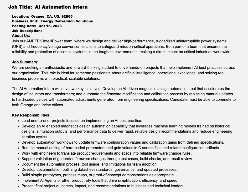
The posting describes six problems: magnetics design iterations, hand-edited firmware constants, specs that aren't machine-usable, provable validation, undocumented process, and responsible AI adoption. This demo addresses the first two (magnetics: the data step and first-pass sizing; firmware constants: end to end) and supports the next four.
| # | Assumption | Why I think so | Confidence | How to check |
|---|---|---|---|---|
| A1 | Calibration and config constants live in C source (#defines / const tables) | The posting says so | High | Read one product's source |
| A2 | Many constants derive from data sheet ratings | Data sheet fields map cleanly to limits (1500 VA ÷ 120 V × 1.20 = 15 A) | Medium | Trace ten constants to their origin |
| A3 | Alternate-component substitutions change sense gains | Engineering postings: "qualify new, or alternate components" | Medium | Ask how the last substitution was handled |
| A4 | The processor is a TI C2000 part | Posting asks for TI chipsets; public site says DSP firmware | Medium | Look at a board |
| A5 | Specs are not machine-readable today | All three data sheets checked contain an internal inconsistency | Medium | See the spec source of truth |
| A6 | Some calibration is per unit at a test station | The phrase "calibration gains" | Low | Ask production test |
| A7 | Past magnetics designs live in drawings and spreadsheets, not a database | The posting asks for a tool trained on "historical designs" | Medium | Ask for ten recent inductor drawings |